
Find What Fits Your Harley
Sony Single DIN Installation Guide | 1998-2013 Road Glide
Please follow these installation tips when you're ready to install your new
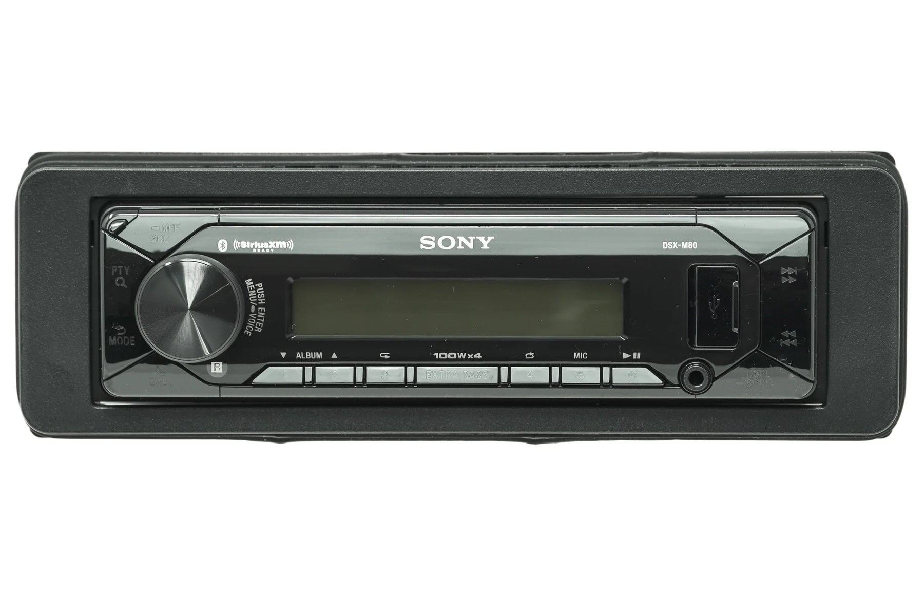
Sony Single DIN Radio Bundle
in your 1998-2013 Harley-Davidson® Road Glide.
Tools Needed:
- ½ inch wrench
- T25 torx bit
- 3/16-inch allen
- Zip ties
- Cutters
- Fender cover
Remove the outer fairing:
- Cover the front fender with a fender cover.
- Use a ½ inch wrench to remove the nuts that secure the turn signals from the inside of the forks.
- Depress the tab and remove the turn signal wiring harness from each light.
- Remove the six T25 bolts that secure the inner fairing.
- 1 set towards the top of the inner fairing.
- 1 set in the middle along the outside edge of the inner fairing.
- 1 set at the bottom along the outside of the inner fairing.
- Lift up and out on the outer fairing.
- Unplug the headlight harness and set the outer fairing to the side.
Removing the factory radio:
- Disconnect all wiring harnesses from the back of the radio.
- Remove the four 3/16 inch allen screws that secure the radio.
- Remove the radio towards the gas tank.
Installing your new Sony Single DIN radio:
- Insert the radio into the inner fairing.
- Ensure that the four factory mounting holes are lined up and secure with the four 3/16th inch allen bolts.
- Connect the harness from the back of the radio to the factory main connection.
- Insert the harness, swivel the locking tab until it clicks and locks into place.
- Connect the AM/FM antenna to the radio.
- Connect the provided microphone to the radio.
- We recommend mounting the provided microphone to the top in the inner fairing just behind the windshield. This will give you the ability to use hands free calling and the placement will reduce wind noise as much as possible.
- You have the option to mount the pre-connected USB where you prefer.
- One recommend location inside the storage cubby on the right side of the inner fairing. This will require drilling a 1-inch hole in the back side of the cubby large enough to pass the USB wire through.
- The USB wire comes with a grommet that will secure the USB in the hole.
Test the function of the radio:
- Make sure that your key fob is near the motorcycle and switch the ignition to accessory power.
- Allow the head unit to power on completely.
- Remove the handlebar control module from the installation parts bag and connect the wire labeled SWC to the module.
- While still in accessory power, connect the ASWC-1 module to the 12-pin connector on our harness.
- Look for rapidly flashing lights to begin flashing in the indicator window on the top of the module.
- Immediately then pulse (press, release, press, release, continue pattern) the volume up button until you receive a solid light in the indicator window.
- When the light goes solid, release the button and test your functions on your hand controls.
- If your hand controls didn't initialize correctly, use a small pick tool, screwdriver, or paper clip to depress the reset button (other small hole that does not contain the light)
- When the reset button is pressed, the indicator light should begin flashing again, and at this time hold the volume up button again until the light goes solid.
- Check your hand controls to ensure they're functioning. Repeat the reset process if they are not.
Replacing the outer fairing:
- Secure any loose wire with zip ties.
- Connect the headlight harness.
- Place the outer fairing back on the motorcycle ensuring that it is hanging on the factory support bracket.
- Replace the six T25 bolts that secure the inner and outer fairing.
- 1 set towards the top of the inner fairing.
- 1 set in the middle along the outside edge of the inner fairing.
- 1 set at the bottom along the outside of the inner fairing.
- Reconnect the wiring harnesses for the turn signals.
- Use a ½ inch wrench to replace the nuts that secure the turn signals from the inside of the forks.